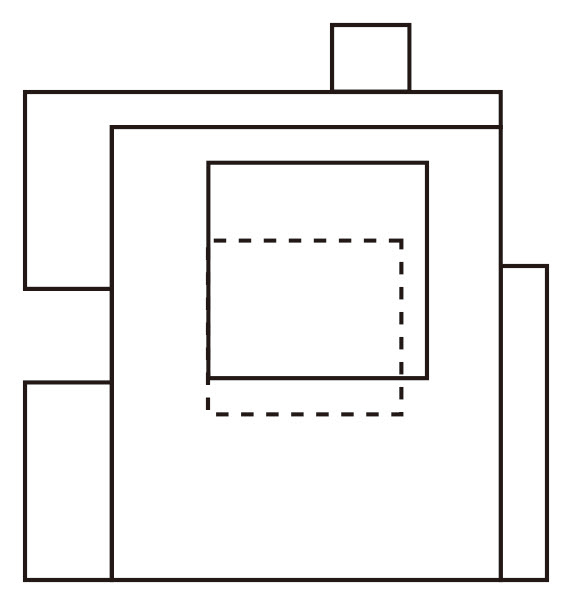
Fig. 1 - Parti Plan Diagram
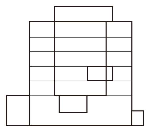
Fig. 2 - Parti Sectional Diagram
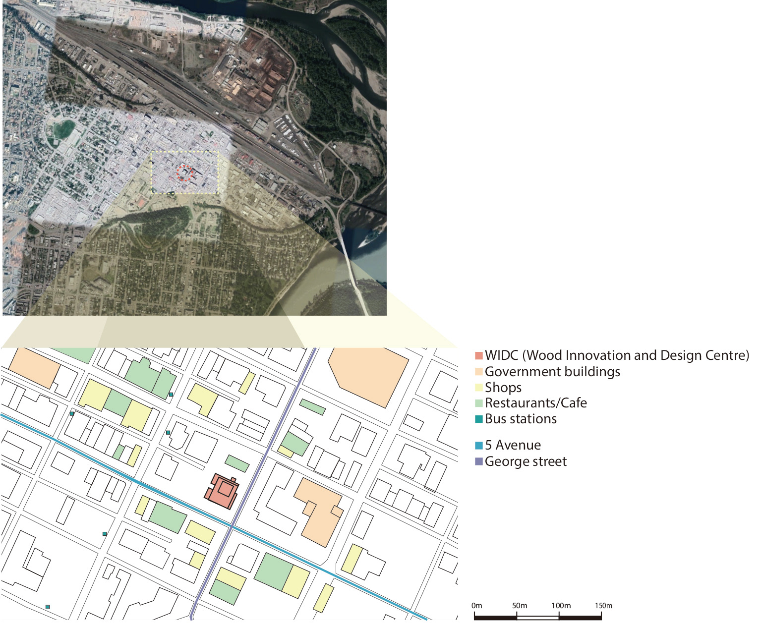
Fig. 3 - Site aerial view (Google Earth), Fig. 4 - Site Analysis Plan
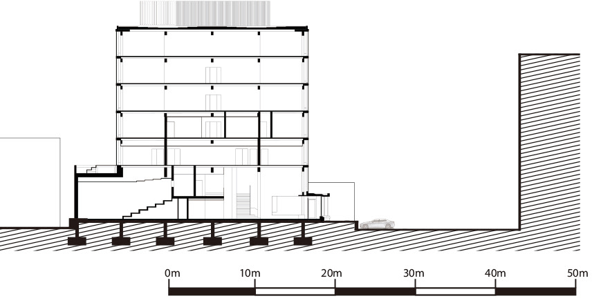
Fig. 5 - Site Analysis section
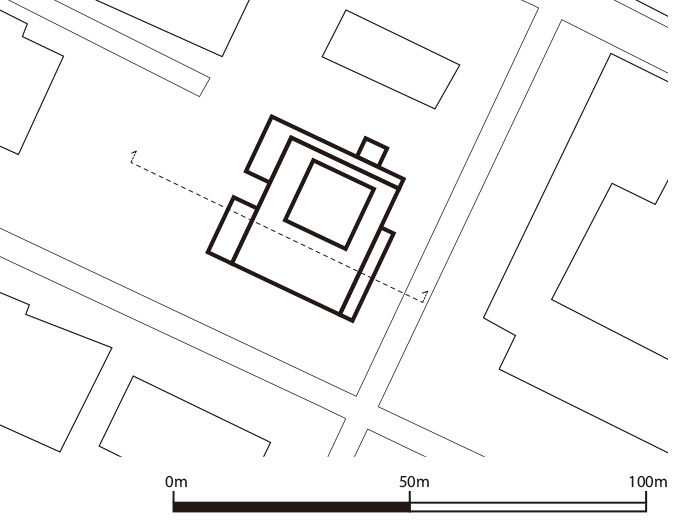
Fig. 6 - Site Analysis Plan
Fig. 7 - Plans + Key Section
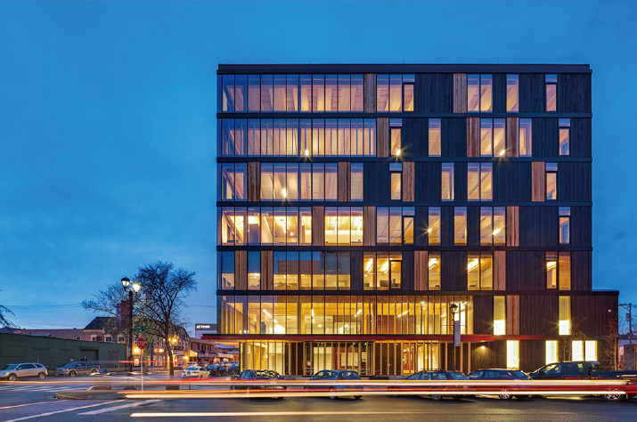
Fig. 8 - Photograph of the WIDC (MGA, n.d.)
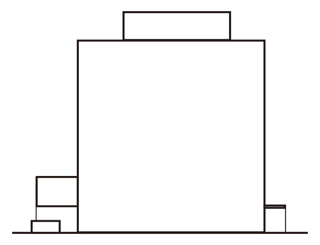
Fig. 9 - Massing diagram
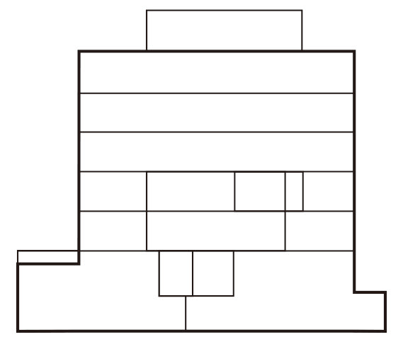
Fig. 10 - Plan to Section diagram
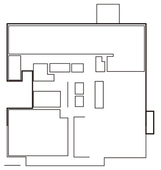
Fig. 10 - Plan to Section diagram
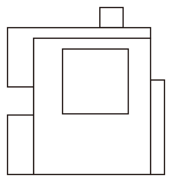
Fig. 11 - Additive Subtractive
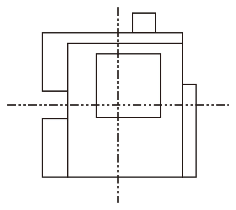
Fig. 12 - Symmetry & Balance

Fig. 13 - Circulation To Use Diagram

Fig. 14 - Hierarchy Diagram

Fig. 15 - Programme Analysis Diagrams

Fig. 16 - Public + Private
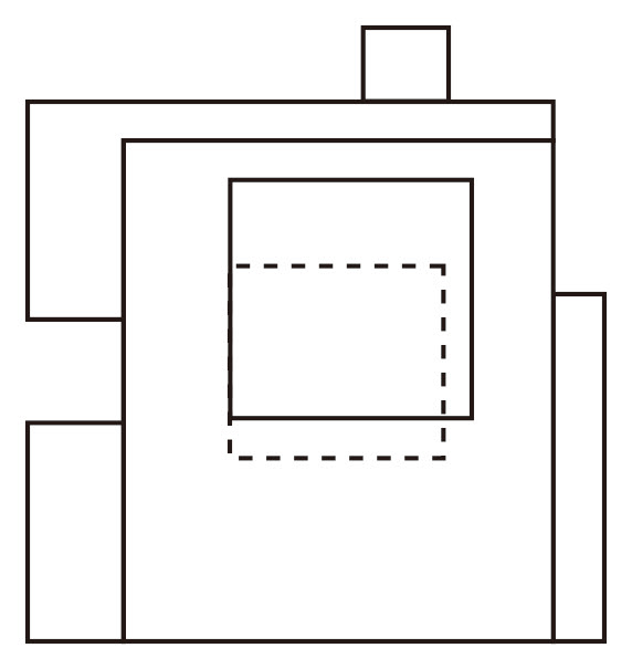
Fig. 17 - Parti Diagram
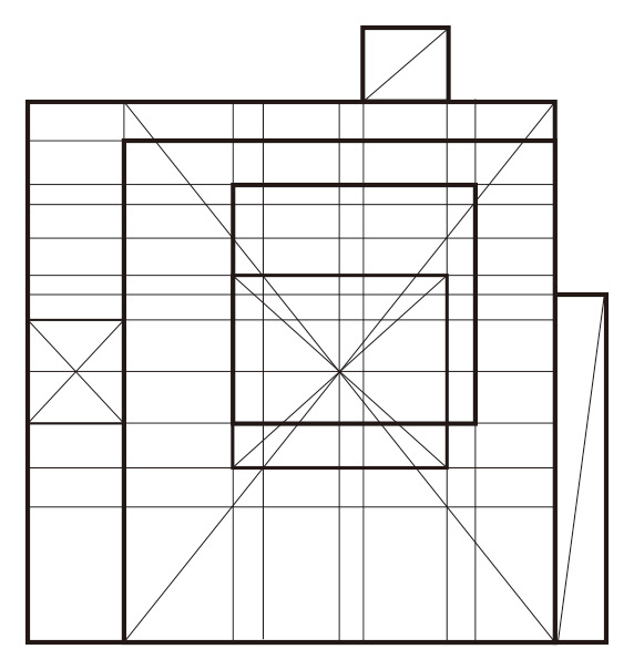
Fig. 18 - Geometry Diagrams

Fig. 18 - Geometry Diagrams

Fig. 19 - 3D model: Grid shaped glulam structure + CLT panels
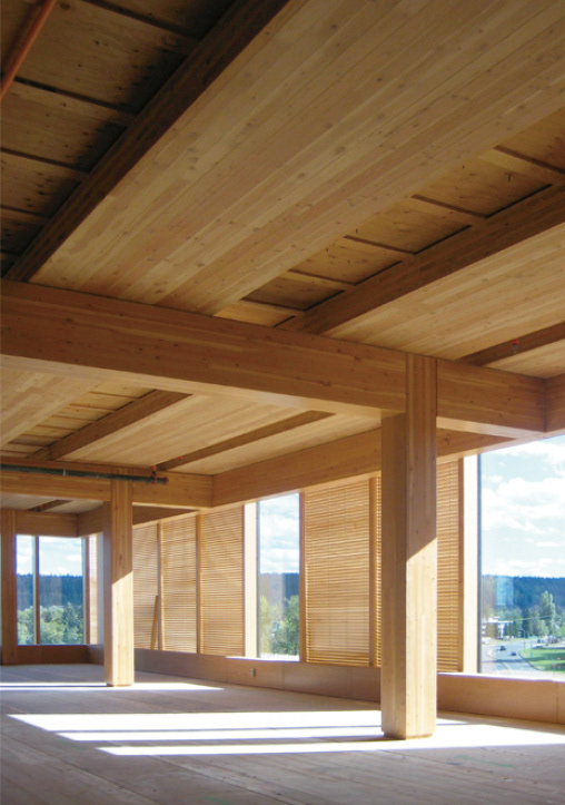
Fig. 20 - Photograph of the open ceiling and interior (MGA, n.d.)

Fig. 21 - 3D model: Building envelope

Fig. 22 - Elevation drawing: Building envelope

Fig. 23 - Photographe of the building envelope (MGA, n.d.)
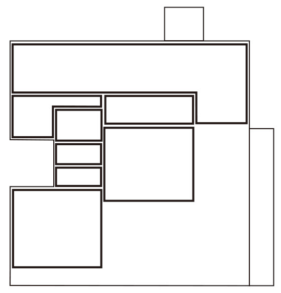
Fig. 24 - Unit to Whole Diagram
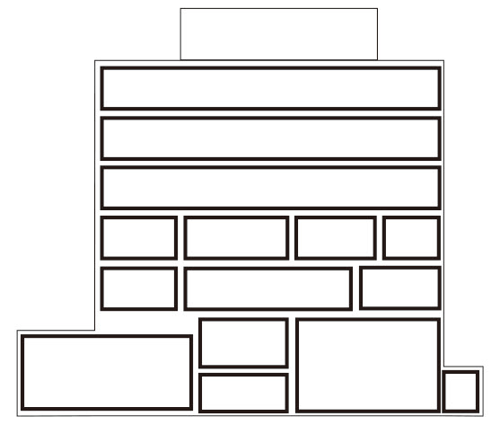
Fig. 25 - Repetitive Diagram
Fig. 26 - Photograph of the flooring/ceiling system (Boddy, 2015),(MGA, n.d.)
Fig. 27 - 3D models of the CLT floor/ceiling system
Fig. 28 - Section in detail: Floor/ ceiling as a solution for the design objective
Fig. 29 - Photograph of the dropped kerb (Googlemap), Fig. 30 - Approved document M Vol.2 p.17 - Tactile paving
Fig. 31 - Diagrams of the suggestion for the tactile paving

Fig. 32 - Approved document M Vol.2 p.18 - Car park

Fig. 33 - Photograph of the car park for disabled people (Googlemap)
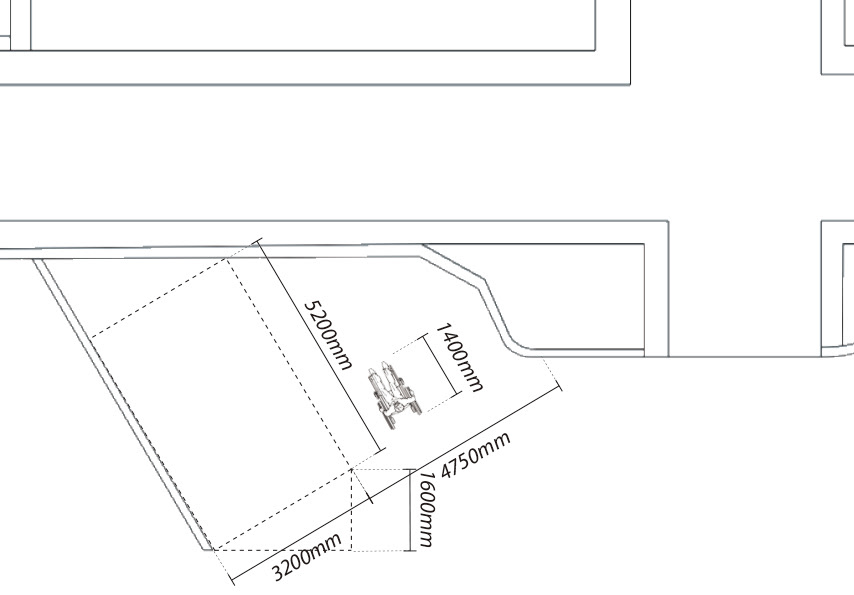
Fig. 34 - Diagram of the car park measurements

Fig. 35 - Approved document M Vol.2 p.21 - Corduroy
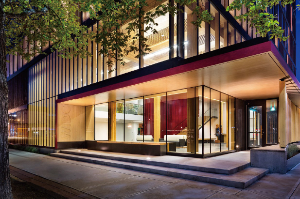
Fig. 36 - Photograph of the stairs (MGA, n.d.)

Fig. 37 - Diagrm of the suggestion for the corduroy

Fig. 38 - Diagram for the location of accessible entrances and route, Fig. 39 - Photograph of another car park (Goolge map)
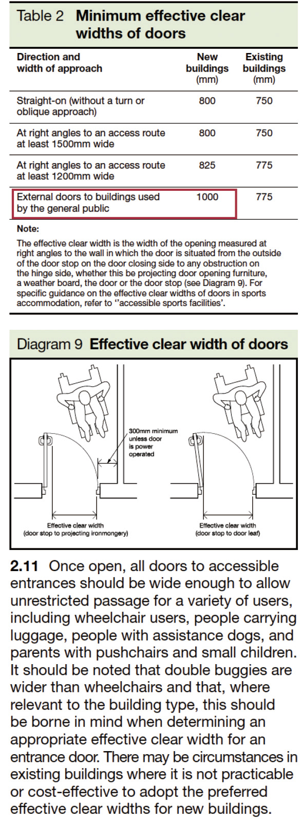
Fig. 40 - Approved document M Vol.2 p.25 - door
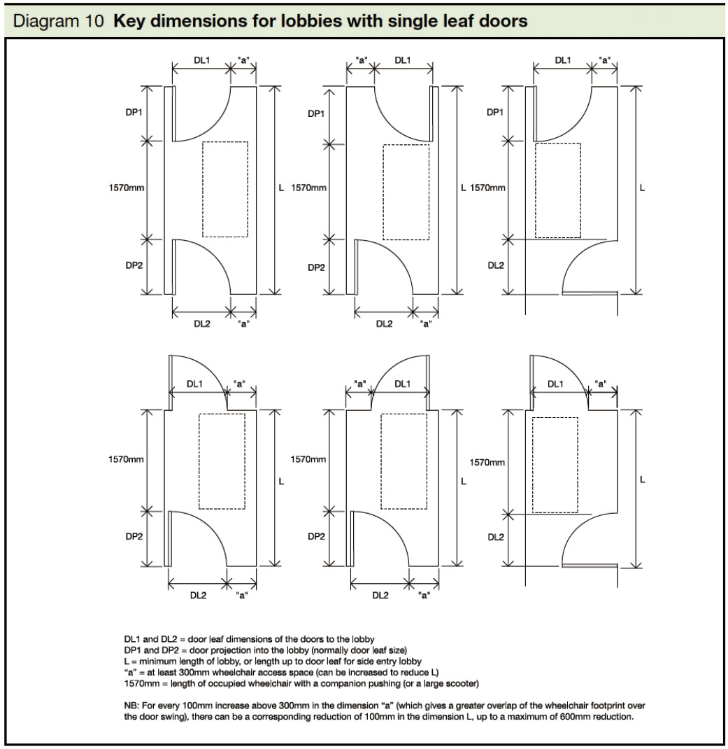
Fig. 41 - Approved document M Vol.2 p.28 - door
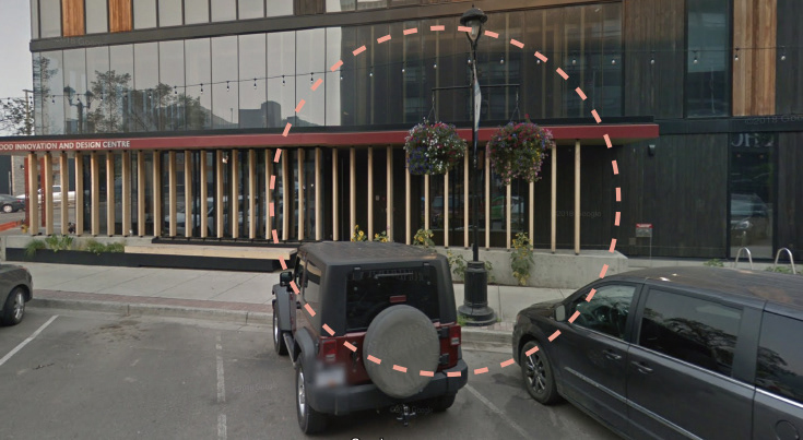
Fig. 42 - Photograph of the accessible entrance for wheelchair users (Goolge map)

Fig. 43 - Diagram of the accessible entrance measurements
Fig. 44 - Structure Diagram

Fig. 45 - Iso 3D model - primary, secondary, tertiary structure

Fig. 46 - 3D model - primary structure: glulam posts and beam (typical column-to-column connection and the attachment of beams
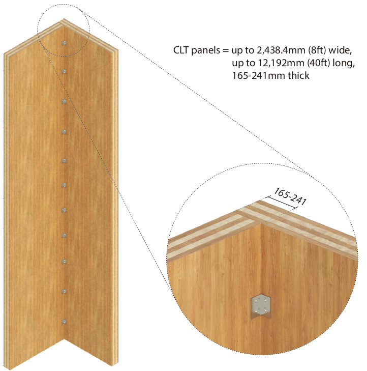
Fig. 47 - 3D model - primary structure: CLT panel walls at core with angled clips connection
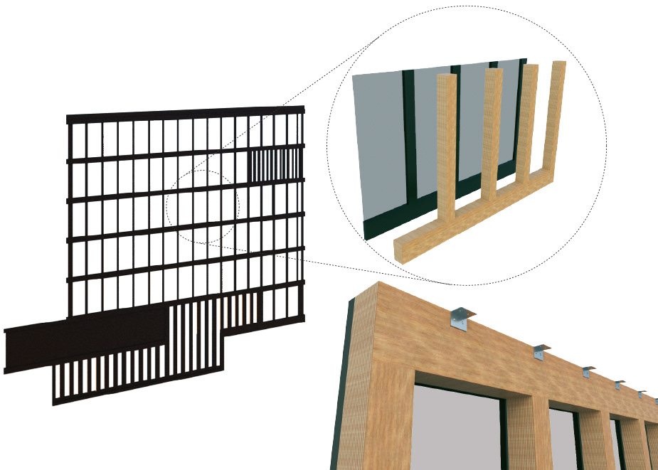
Fig. 48 - 3D model - secondary structure: glazed facade with LVL mullions
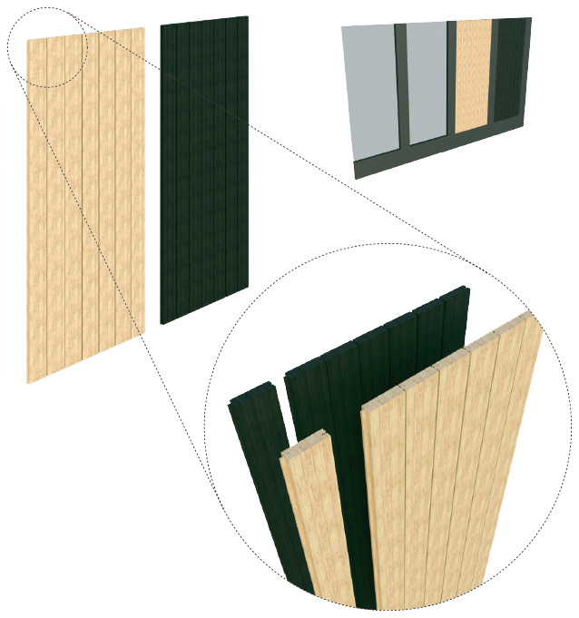
Fig. 49 - 3D model - tertiarystructure: bark envelope (charred wood panels and cedar wood panels)

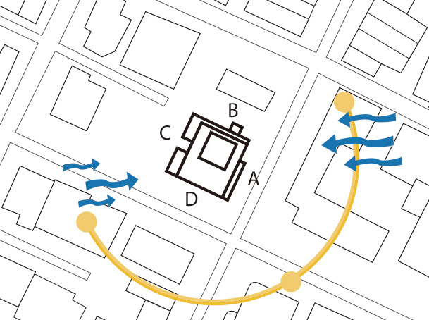
Fig. 50 - Parti site plan: Orientaion + Natural light + Winds

Fig. 51 - 3D model: building envelope
Fig. 52 - Elevation: building envelope (glazing area + wood panels)
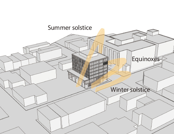
Fig. 53 - Sun orientation

Fig. 54 - Sun infiltration at 12pm (noon)
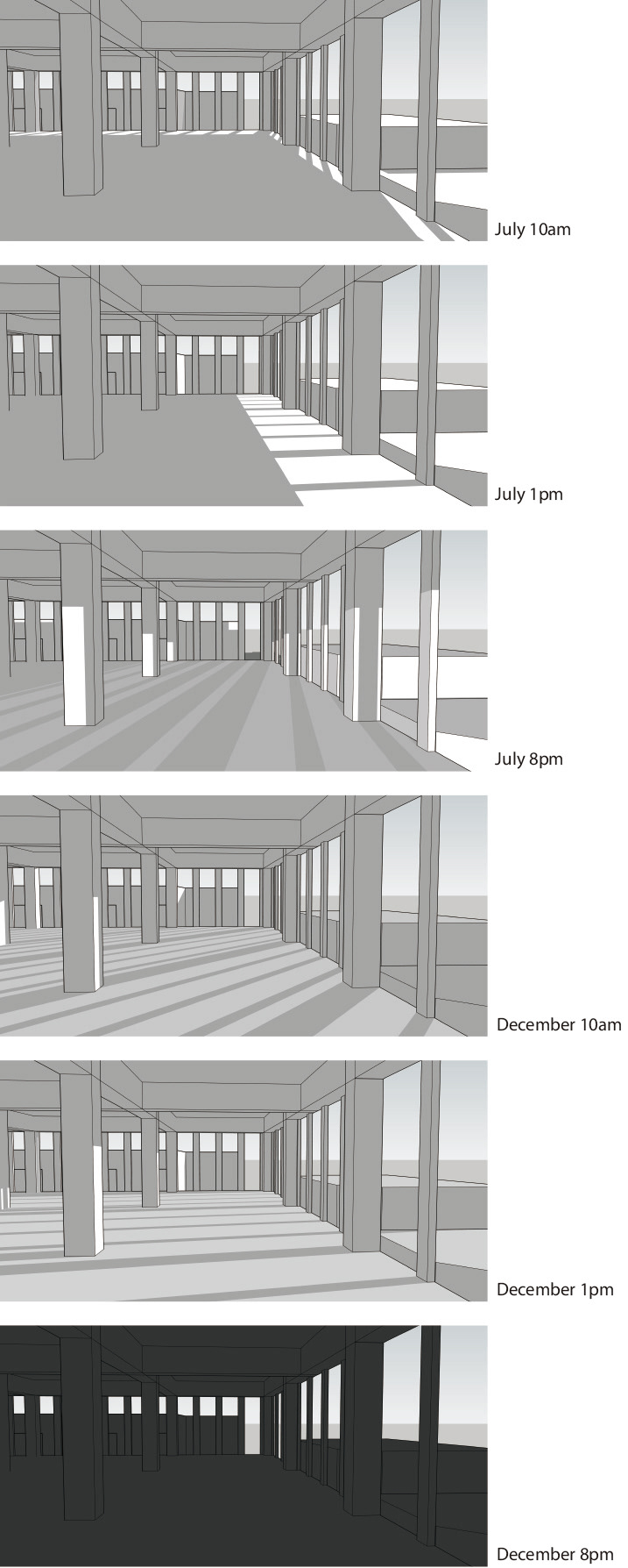
Fig. 55 - Depth of shadow + sunlight

Fig. 56 - Parti site plan diagram - Topography
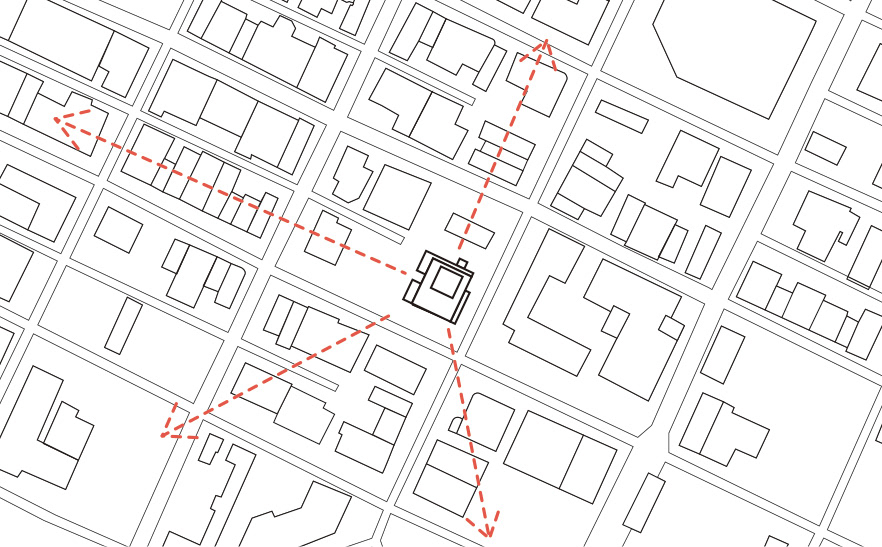
Fig. 57 - Parti site plan diagram - view from the building
Fig. 58 - Iso diagram and elevation: Heat Loos Form Factor of the building + glazed openings to total facade area

Fig. 59 - Parti sectional diagram: Ventilation
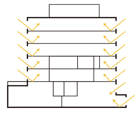
Fig. 60 - Parti sectional diagram: Natural daylight
Fig. 61 - District energy system of Prince George
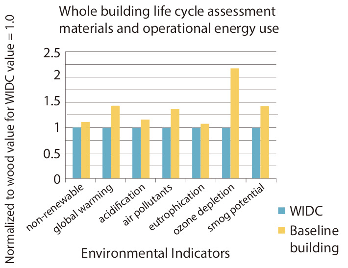
Fig. 62 - Diagram of the building life cycle assessment (Naturally:Wood, 2019)
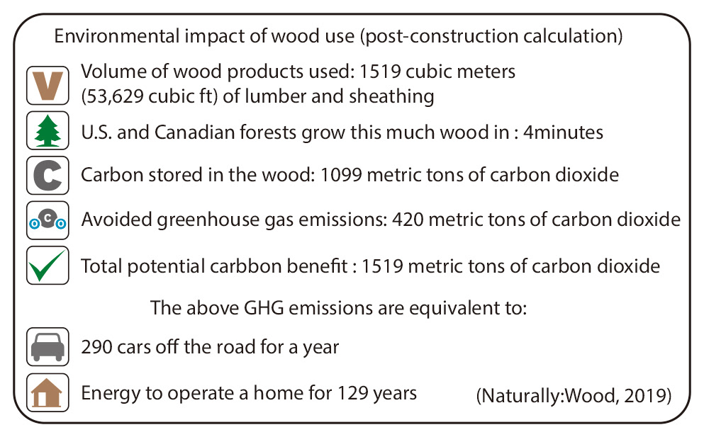
Fig. 63 - Diagram of the environmental impact: wood use
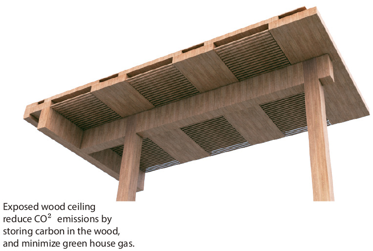
Fig. 64 - 3D model: exposed wood structure (ceiling) - CO² emissions
Fig. 65 - Building element: exterior SIPs walls with cedar cladding
Fig. 66 - Building element - exterior curtain wall section diagram
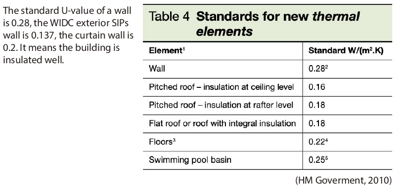
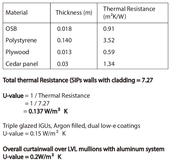
Fig. 67 - Approved document L2B
